
MR-DIO4/2-IP65 Modbus RTU
Description
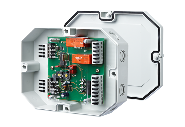
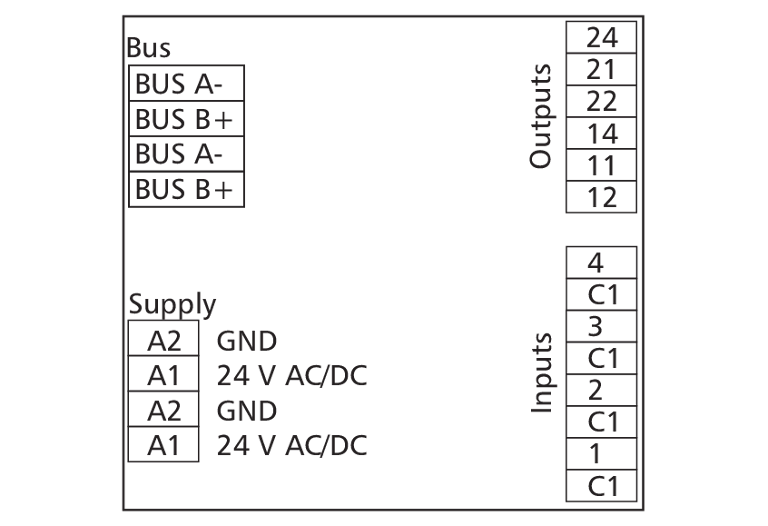
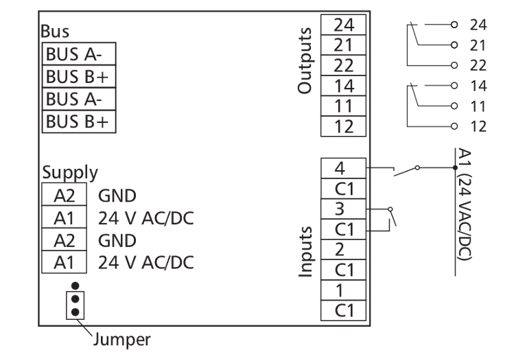
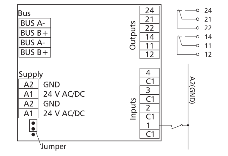
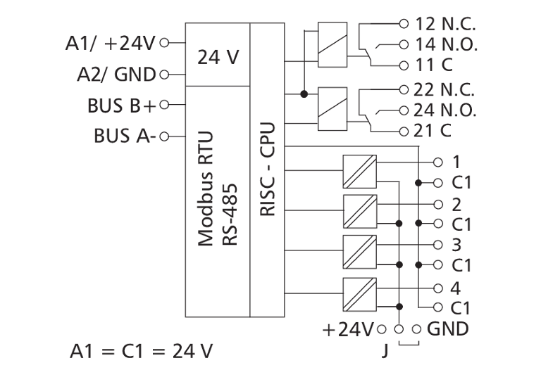
The Modbus module in an IP65 housing with 4 digital inputs and 2 relay outputs was developed for decentralized switching tasks. It is suitable for accommodating, for example, light switches and window contacts in a room, switching two light strips or controlling louvers. It can also be used to control 2 motorized fire dampers. In this case it is necessary to protect the relay contacts by appropriate load-dependent measures. The inputs can be used as contact or voltage inputs. The inputs and outputs can be switched and scanned by means of standard registers via a Modbus master. Module address, bit rate and parity are set by means of two address switches.
Technical Data
General Data
Modbus RTU
00 to 99
RS485 (two-wire bus)
1200 to 115200 bit/s
24 V AC/DC +/- 10% (SELV)
200 mA (AC) / 75 mA (DC)
100 %
4 x digital
30 V DC
more than 8 V AC/DC
2 changeover contacts (DPDT)
250 V AC
8 A / output
10 A / output
80 A (less than 20 ms)
Green, red and yellow LED
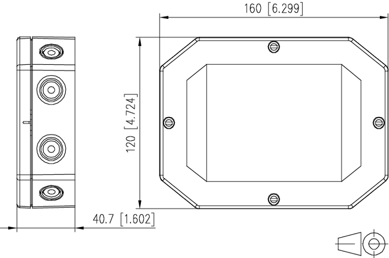
160 x 40 x 120 mm
350 g
-5 °C to +55 °C
-20 °C to +70 °C
IP65 / IP20
Check US distributor inventory
Accessories
Part number
1108331326IP
4250184135630
Downloads
- Data sheet
- Brochure (Intelligent system components with integrated application software)
- Brochure (Modbus RTU components)
- REACh Statement
- 3D-Data - Registration required -
- Mounting note (1108331326IP MR-DIO4/2-IP)
- Mounting note (Safety Instructions multilingual )
- Software manual (Modbus Software-Handbuch)
FAQ's
What can I do if the red ERROR LED on the module lights up or there is no communication?
There are several possible causes, please check the following:
- Operating voltage (A1 / A2) connected and sufficient for the device.
- BUS (A- / B+) connected and not reversed. Pay attention to (- / +), not to A/B.
- Address (rotary switch) set correctly, must not occur twice or be 0.
- Bit rate and parity (rotary switch) set correctly, only possible in programming mode (see mounting note).
- Shielded and twisted cable used.
- Termination resistor (120 Ω) set on both sides.
- Bias resistors available once on the BUS.
- Timeout high enough for all participants to respond (approx. 10 ms).