|

BMT-F-DIO4/2 BACnet MS/TP

911507
909350
913315
913316
910158
909349
Description

The BACnet MS/TP module with 4 digital inputs and 2 relay outputs with manual control was developed for decentralized switching tasks. It is suitable for accommodating, for example, light switches and window contacts in a room, switching two light strips or controlling louvers. It can also be used to control 2 motorized fire dampers. In this case it is necessary to protect the relay contacts by appropriate load-dependent measures. The inputs can be used as contact or voltage inputs. The inputs and outputs can be switched and scanned by means of standard objects via a BACnet client. The module address and the baud rate are set by means of two address switches on the front. Suitable for decentralized mounting on DIN TH35 rail according to IEC 60715 in electrical distribution cabinets.

  • Connection with spring clamp terminal blocks (push-in)
logo_btl logo_culs_listed

BACnet is a registered trademark of ASHRAE. ASHRAE does not endorse, approve or test products for compliance with ASHRAE standards. Compliance of listed products to the requirements of ASHRAE Standard 135 is the responsibility of BACnet International (BI). BTL is a registered trademark of BI.

Technical Data
General Data
BACnet MS/TP
00 to F9
RS485 (two-wire bus)
9600 to 115200 bit/s
24 V AC/DC +/- 10 % (SELV)
80 mA (AC) / 40 mA (DC)
100 %
4 x digital
30 V AC/DC
more than 7 V AC/DC
2 x changeover contacts (DPDT)
250 V AC
16 A / relay
80 A (less than 20 ms)
Green, red and yellow LED
50 x 69.3 x 60 mm
126 g
-5 °C to 55 °C
-20 °C to 70 °C
IP40 / IP20
Check US distributor inventory
Accessories
Accessory of
Part number
110883132670
4251394620794
Downloads
FAQ's

What can I do if the red ERROR LED on the module lights up or there is no communication?

There are several possible causes, please check the following:

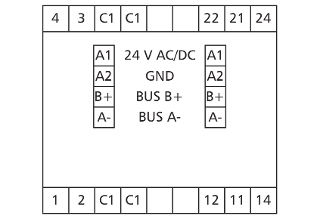
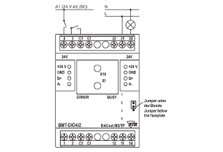
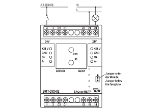
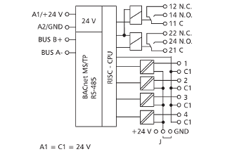
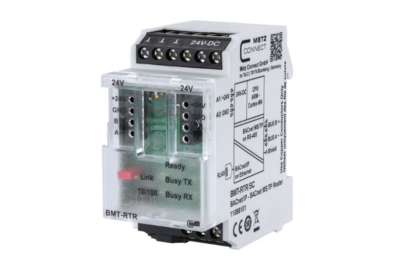
- Operating voltage (A1 / A2) connected and sufficient for the device.
- BUS (A- / B+) connected and not reversed. Pay attention to (- / +), not to A/B.
- Address (rotary switches) set correctly, must not occur twice or be 0.
- Bit rate (rotary switches) set correctly, only possible in programming mode (see mounting note).
- Shielded and twisted pair cable used.
- Termination resistor (120 Ω) set on both sides.
- Bias resistors available once on the BUS.
- Max Master as high as the number of physical master I/Os on the BUS.
- Max Frame high enough for all answers from participants to get through (BMT-RTR setting).

× Do you have any questions?