

Which sensors can be connected to the BMT-AI8?
Sensors in range from 40 Ohm to 4 MOhm and 0 to 10 V, already stored types (e.g. PT1000) are found in the software manual, a user-defined temperature curve can also be created.


Highly specialized and high-performance network solutions.
I/O components for automation in buildings, systems and machinery.
From the field level to the data center.
From the house transfer point through fiber optic and copper cabling to WLAN solutions.
Pre-assembled compact solutions and MPO/MTP® plug connections and MTP®/MPO cable assemblies.
Easily download our catalogs, brochures, product information and application notes.
All documents such as certificates, terms and conditions, etc.
Simply and quickly add data sheets and images to a list and download them as a ZIP file.
Check the inventory of North American Distributors.
Easily order your samples.
Complete range of product and mounting videos – watch or download.
Fast and safe to your destination – your individual cable and patch panel.
News about METZ CONNECT products, as well as offers, promotions, invitations and other interesting topics.
Take a tour of our 360-degree product experience and get to know METZ CONNECT products in their application context.
Overview of our national US distributors.
Find your right contact person or distributor.
Feel free to contact us.
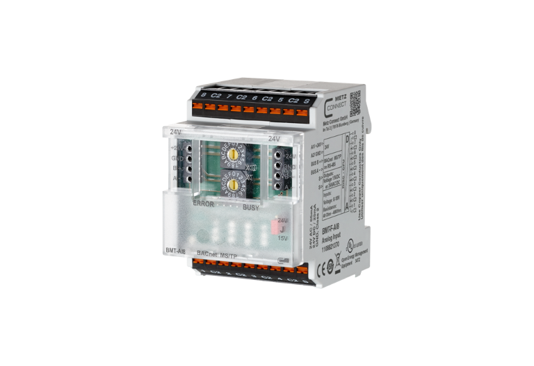

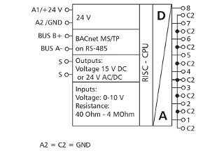
The BACnet MS/TP module with 8 individually configurable resistance or voltage inputs was developed for decentralized switching tasks. It is suitable for detecting resistances and voltages of, for example, passive and active temperature sensors, electrical vent and mixing valves, valve positions, etc. The inputs can be configured universally by means of standard objects via a BACnet client. The module is addressed and the baud rate is set by means of two address switches on the front. Suitable for decentralized mounting on DIN TH35 rail according to IEC 60715 in electrical distribution cabinets.
BACnet is a registered trademark of ASHRAE. ASHRAE does not endorse, approve or test products for compliance with ASHRAE standards. Compliance of listed products to the requirements of ASHRAE Standard 135 is the responsibility of BACnet International (BI). BTL is a registered trademark of BI.
Which sensors can be connected to the BMT-AI8?
Sensors in range from 40 Ohm to 4 MOhm and 0 to 10 V, already stored types (e.g. PT1000) are found in the software manual, a user-defined temperature curve can also be created.
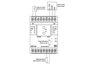
Can passive three or four wire sensors be connected to the BMT-AI8?
No, only possible with the EWIO2.
What can I do if the red ERROR LED on the module lights up or there is no communication?
There are several possible causes, please check the following:
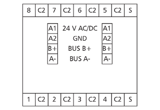
- Operating voltage (A1 / A2) connected and sufficient for the device.
- BUS (A- / B+) connected and not reversed. Pay attention to (- / +), not to A/B.
- Address (rotary switches) set correctly, must not occur twice or be 0.
- Bit rate (rotary switches) set correctly, only possible in programming mode (see mounting note).
- Shielded and twisted pair cable used.
- Termination resistor (120 Ω) set on both sides.
- Bias resistors available once on the BUS.
- Max Master as high as the number of physical master I/Os on the BUS.
- Max Frame high enough for all answers from participants to get through (BMT-RTR setting).
Which sensors can be connected to the BMT-AI8?
Sensors in the range from 40 Ohm to 4 MOhm and 0 to 10 V, the following types are already stored (see below), a user-defined temperature curve can also be created.
PT100
PT500
PT1000
NI1000-TC5000
NI1000-TC6180
BALCO500
KTY81_110
KTY81_210
NTC1k8-Thermokon
NTC5k-Thermokon
NTC10k-Thermokon
NTC20k-Thermokon
LM235Z
NTC10k-Carel
NTC5k-Schneider
NTC30k-Schneider
KP250