



MB-DIO4/2-IP Modbus/BACnet 24V AC/DC
Description
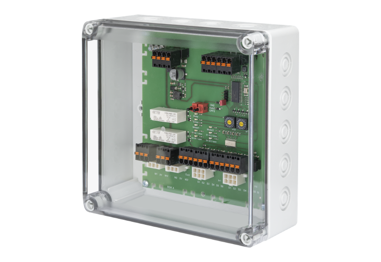
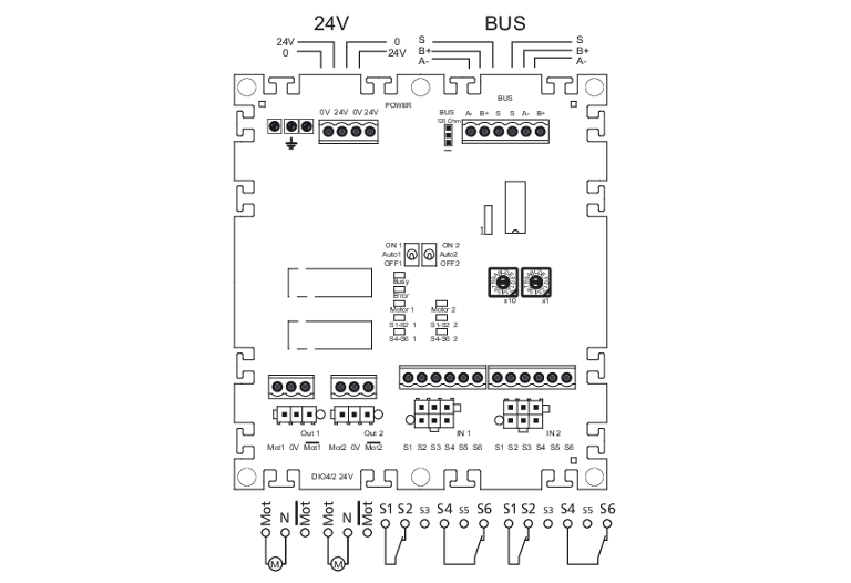
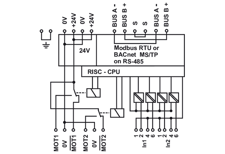
The MB-DIO4/2-IP 24 V module in IP65 housing with 4 digital inputs, as well as 2 relay outputs, is suitable for the inclusion of decentralized signal contacts and the control of decentralized switching tasks. As signal contacts, e.g. window contacts or the positions of ventilation flaps, etc. can be detected and controlled for switching tasks, e.g. motorized actuators or light bands, etc. Actuators with AMP connectors (AMP brand from TE Connectivity) can be connected directly to the MB-DIO4/2-IP 24 V. Depending on the operating mode, the module can be switched or requested with Modbus standard registers or with BACnet objects.
- for the control of up to two actuators, e.g. fire dampers
- Connection options for actuators with AMP plug-in connector or open connection lines with pluggable push-in technology
- Supply voltage is also switching voltage
- Relay output suitable for inrush current 65 A < 20 ms (NO), continuous current 6A, total current 8A
- generous space for installation - no additional distribution box required

BACnet is a registered trademark of ASHRAE. ASHRAE does not endorse, approve or test products for compliance with ASHRAE standards. Compliance of listed products to the requirements of ASHRAE Standard 135 is the responsibility of BACnet International (BI). BTL is a registered trademark of BI.
Technical Data
General Data
Modbus RTU / BACnet MS/TP
00 to EF
00 to EF
1200 to 115200 bit/s
19200 Bit/s Even
RS485 (two-wire bus)
24 V AC/DC +/- 10% (SELV)
80 mA (AC) / 25 mA (DC)
1
4
Contact
2 changeover contacts (DPST)
6 A per relay (65 A for 20 ms NO) max. current 8 A
175 x 175 x 75 mm
630 g
any
-5 °C to 55 °C
-20 °C to 70 °C
IP65
LED green, red, yellow
Check US distributor inventory
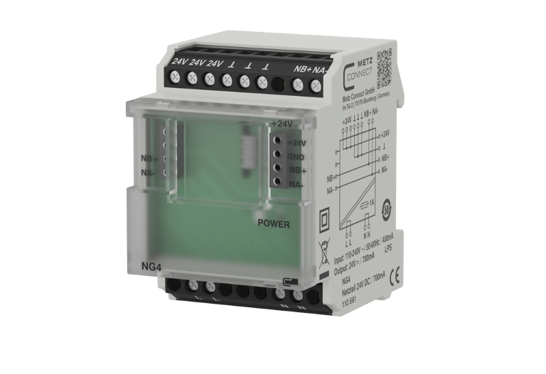
Accessories
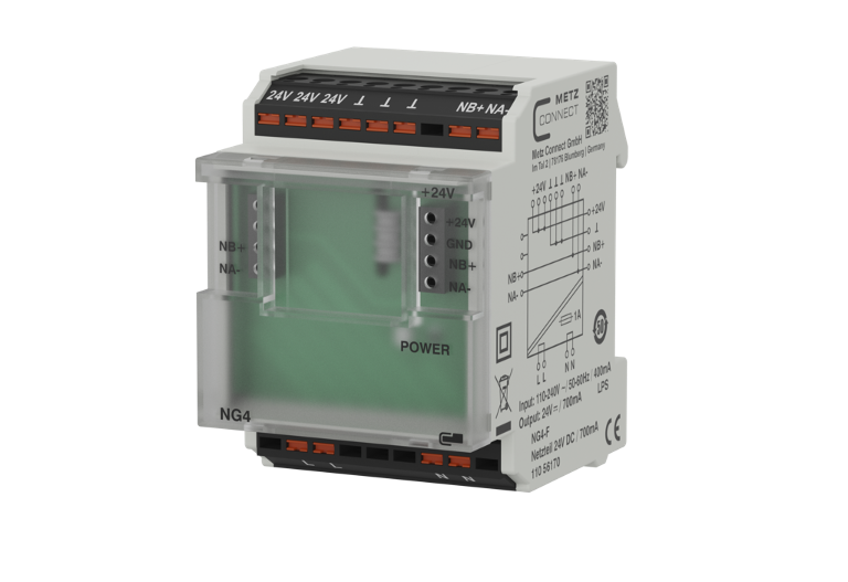
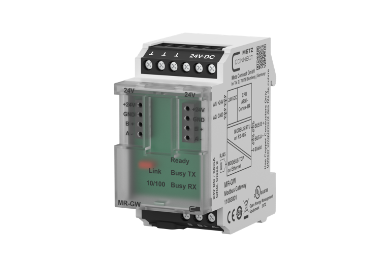
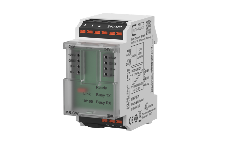
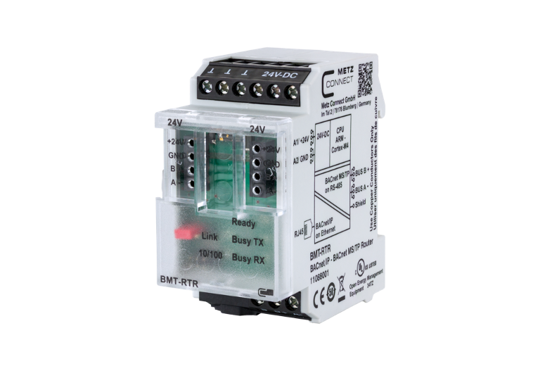
Part number
1108121326IP
4251394658360
Downloads
- Brochure (Modbus Gateway - Network connection of Modbus RTU fieldbus components)
- Brochure (Modbus I/O Mixing Module)
- Brochure (BACnet/IP and BACnet/SC Router - Data Security with Secure Connect)
- Mounting note (1108111326IP, 1108121326IP)
- Mounting note (Safety Instructions multilingual )
- Data sheet
- Software manual (MB-Familie Software-Handbuch)
FAQ's
What can I do if the red ERROR LED on the module lights up or there is no communication?
There are several possible causes, please check the following:
- Operating voltage (A1 / A2) connected and sufficient for the device.
- BUS (A- / B+) connected and not reversed. Pay attention to (- / +), not to A/B.
- Address (rotary switch) set correctly, must not occur twice or be 0.
- Bit rate and parity (rotary switch) set correctly, only possible in programming mode (see mounting note).
- Shielded and twisted cable used.
- Termination resistor (120 Ω) set on both sides.
- Bias resistors available once on the BUS.
- Timeout high enough for all participants to respond (approx. 10 ms).
What can I do if the red ERROR LED on the module lights up or there is no communication?
There are several possible causes, please check the following:
- Operating voltage (A1 / A2) connected and sufficient for the device.
- BUS (A- / B+) connected and not reversed. Pay attention to (- / +), not to A/B.
- Address (rotary switches) set correctly, must not occur twice or be 0.
- Bit rate (rotary switches) set correctly, only possible in programming mode (see mounting note).
- Shielded and twisted pair cable used.
- Termination resistor (120 Ω) set on both sides.
- Bias resistors available once on the BUS.
- Max Master as high as the number of physical master I/Os on the BUS.
- Max Frame high enough for all answers from participants to get through (BMT-RTR setting).

Additional Information

