
MR-DIO4/2-IP65 Modbus RTU 230 V
Description
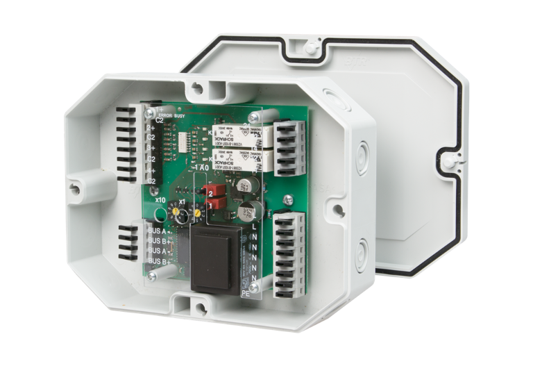
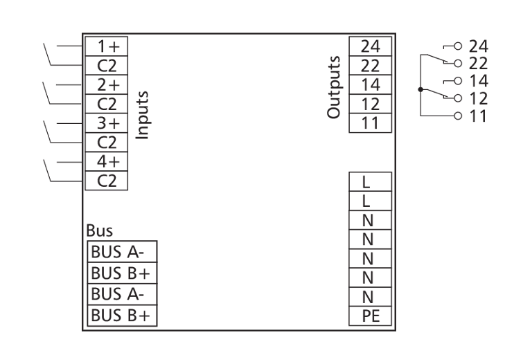
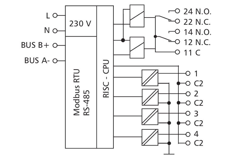
The Modbus module inan IP65 housing with 4 digital inputs and 2 relay outputs with manual control was developed for decentralized switching tasks. It is suitable for accommodating, for example, light switches and window contacts in a room, switching two light strips or controlling louvers. It can also be used to control 2 motorized fire dampers. In this case it is necessary to protect the relay contacts by appropriate load-dependent measures. The inputs have to be connected to potentialfree contacts. The inputs and outputs can be switched and scanned by means of standard registers via a Modbus master. Module address, bit rate and parity are set with two rotary switches. Bit rate and parity are also set by software.
Technical Data
General Data
Modbus RTU
00 to 99
1200 to 115200 bit/s, Factory setting 19200 bit/s Even
RS485 two wire bus with potential equalization in bus or line topology terminate with 120 Ohm
230 V +/- 10 %
12 mA
100 %
4
30 V AC/DC
more than 8 V AC/DC
2 changeover contacts (DPST)
250 V AC
10 A per relay (65 A for 20 ms) max. current via terminal "11" 10 A
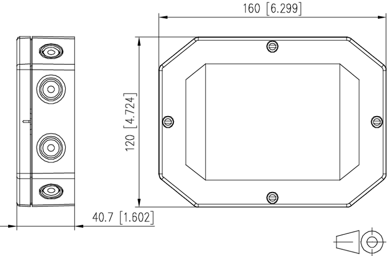
160 x 40.7 x 120 mm
350 g
any
directly on a flat surface 8 knock-out openings for M12 and M16 cable glands
23 °F to 131 °F (-5 °C to 55 °C)
-4 °F to 158 °F (-20 °C to 70 °C)
IP65
green LED
red LED
yellow LED's
Check US distributor inventory
Part number
1108330526IP
4251122197390
Downloads
FAQ's
What can I do if the red ERROR LED on the module lights up or there is no communication?
There are several possible causes, please check the following:
- Operating voltage (A1 / A2) connected and sufficient for the device.
- BUS (A- / B+) connected and not reversed. Pay attention to (- / +), not to A/B.
- Address (rotary switch) set correctly, must not occur twice or be 0.
- Bit rate and parity (rotary switch) set correctly, only possible in programming mode (see mounting note).
- Shielded and twisted cable used.
- Termination resistor (120 Ω) set on both sides.
- Bias resistors available once on the BUS.
- Timeout high enough for all participants to respond (approx. 10 ms).