
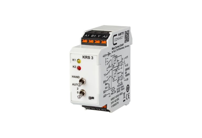
KRS-F-E08 HR3 24 V AC/DC
Description
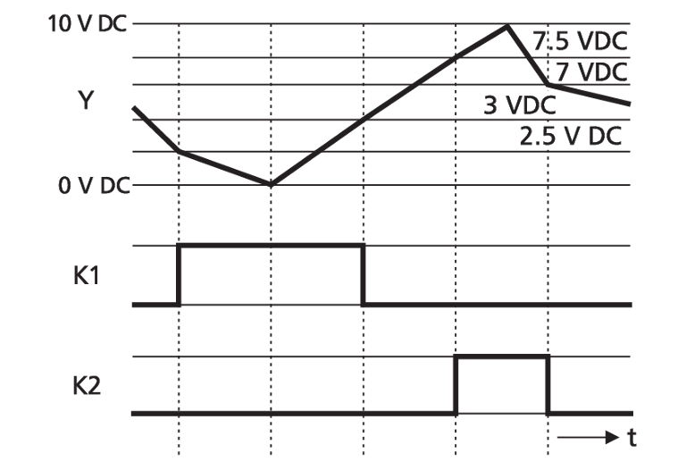
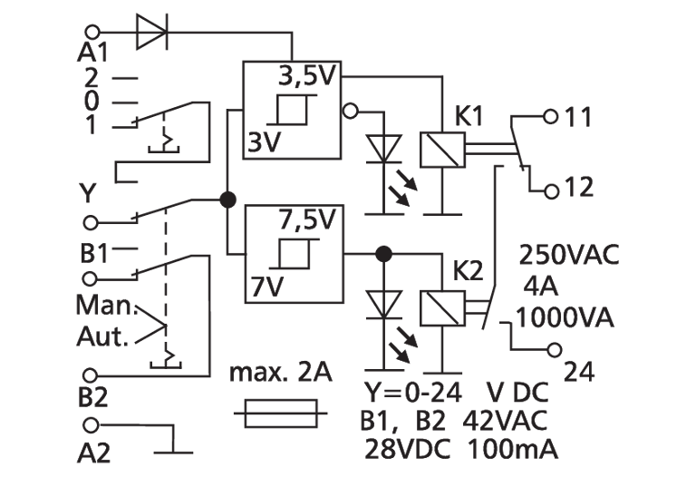
The threshold gate switches units, pumps, fans, burners, etc. As soon as the input voltage reaches the switching threshold, the relay is activated. When the input voltage falls below the switch-off threshold, the relay is released again. The module is designed for a two-level control by means of an analog 0 to 10 V DC control signal.
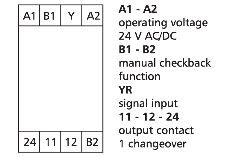
- Connection with spring clamp terminal blocks (push-in)
- Control signal 0 V DC = Level 1 active
- Control signal 5 V DC = No level is active (OFF)
- Control signal 10 V DC = Level 2 active
- with manual control level
Technical Data
General Data
24 V AC/DC
100 mA
35 mA
250 V AC
1 x changeover contact with 0 position
AgSnO2
4 A
1200 cycles/h
1 x 10⁷ switching cycles
1 x 10⁵ switching cycles
Yellow and red LED
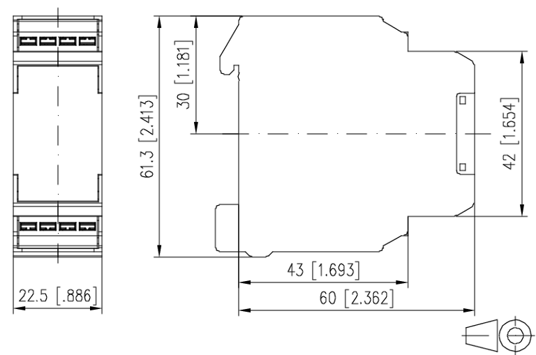
22,5 x 61,3 x 60 mm
70 g
-10 °C to 50 °C
-25 °C to 70 °C
IP40 / IP20
Check US distributor inventory
Part number
11066570
4251394628400
Downloads
- Data sheet
- 3D-Data - Registration required -
FAQ's
What is the difference between the KRS-E08 HR3 and KRS1-E08 HR3?
The Levels of the control signal.
KRS-E08 HR3:
- Control signal 0 V DC = Level 1 active
- Control signal 5 V DC = No level is active (OFF)
- Control signal 10 V DC = Level 2 active
KRS1-E08 HR3:
- Control signal 0 V DC = No level is active (OFF)
- Control signal 5 V DC = Level 1 active
- Control signal 10 V DC = Level 1 and Level 2 active
What does H, R, P and V stand for in the name of the threshold controls, e.g. KRS-E08 HRP?
- H = Hand operation, the module can be controlled via a switch.
- R = Response, the module has an hand operation checkback function.
- P = Potentiometer, the module has an adjustable switch-on voltage and hysteresis.
- V = Verzögerung (delay), the module has a switch-on delay